Moving from incandescence lighting to LED is definitely a good idea, at least from an energy point of view. It may look daunting complicated (and expensive) to change an existing home lighting installation to a genuine LED system. But there are retrofit solutions for every standard you can imagine. Pull the old incandescence or halogen lamp out, push the LED retrofit in and you are done – energy cost cut by 70% or so.
Is it so? Well, regarding energy consumption of the LED lamp – yes. But what’s about the overall benefit? We may calculate this in terms of money spent (for the retrofit LED gadget) versus money saved (for the reduced electricity cost). Or we may try a greener approach by comparing the CO2 footprint of the LED lamp (all the way back to raw materials!) and the CO2 footprint of the saved energy. But wait – my house is running on 100% renewable energy, at least my electricity provider claims this on the bill. So there may be saved energy but this energy seems to have a quite small carbon footprint since it comes from wind, water or solar. Well, there is still a way out of this dilemma: Halogen lamps have a poor lifetime while LEDs run forever!
Is it so? Definitely NOT for many retrofit LED appliances. The power supplies are not designed for LEDs, so every retrofit has to have its own voltage (actually current) regulator on board. Thermal management of the existing installation was designed for lamps not caring about 150°C and higher. LEDs need to run as cool as possible, junction temperatures of 150° and more will severely limit lifetime. And, as always in our commercial world, the product has to be cheap. So you end up with a low-cost current source cramped into the base of a LED retrofit, running terribly hot (measured to the scale of LEDs) – and breaking after about the same service life as an old fashioned halogen lamp.
Still I gave it a try in my house – and collected all the broken retrofits to do some analysis on them. From a CO2 perspective it’s actually the worst thing I could do but curiosity was stronger. Now to the advertised teardown. Today we will look into the remains of a socket GU5.3 reflector LED lamp, once a very common size for cable mounted low voltage halogen systems. Cooling shouldn’t be such an issue there since the lamps are more or less floating in mid-air. Power supply is a 120W toroidal core transformer with nominal 12V. I can’t identify the brand of the lamp – the marking, well, let’s call it “generic”.
My first idea was that less load on the transformer means a higher output voltage which may contribute to the reduced lifetime. So I climbed up to the power supply and was surprised to measure only 12.85V AC on the terminals with the lighter LED-load. Still more than the nominal 12.0 but I dare to call it “within limits”, plus 7% to be precise. By the way, for the input part of the current source inside the lamp a slight over voltage should even be beneficial since it would reduce the current drawn through the input stage. But you will see – such ideas are not relevant.
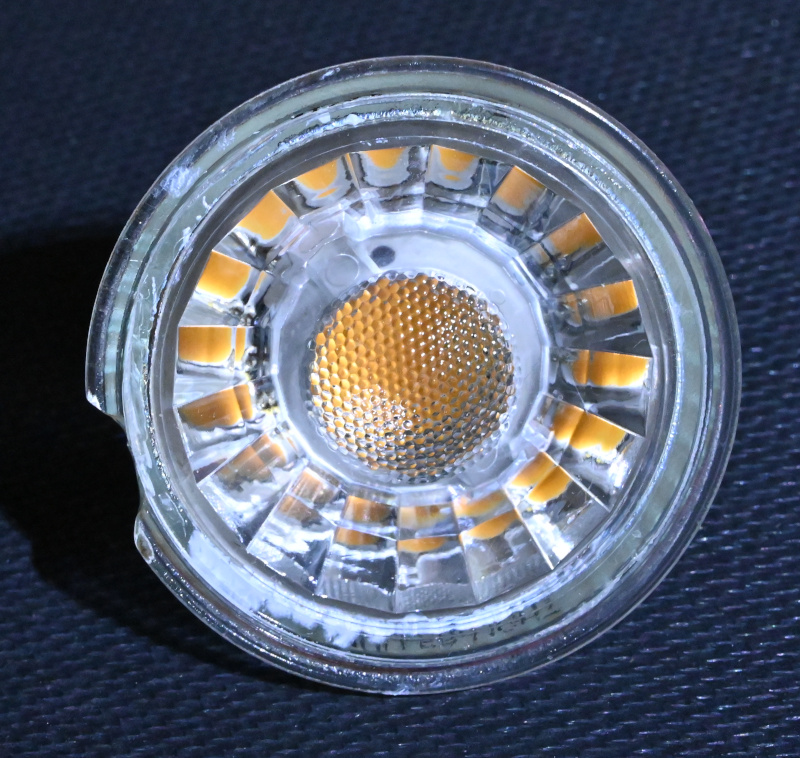
The cover lens looks quite well designed, nothing to complain about. In the end it is just general lighting and not a precision optical instrument. The lens is not tinted to shift the color point of the underlying LED. Good news so far.
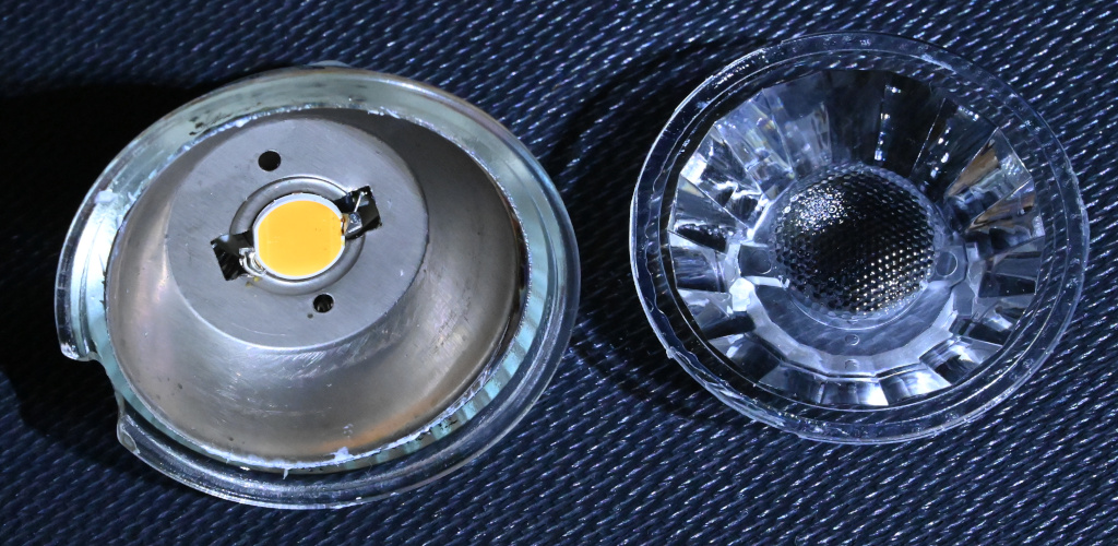
The LED itself seems to be “chip on board” with a silicone converter dispensed on top. Sometimes called “sunny side up-LED” although in this special case the egg white was not really white. Don’t be picky, it’s shiny anyway you say? No, it is important. So close to the emitter light flux is huge and every percent of reflectivity – no matter if specular or diffuse – we lose means a lot of re-absorbed light. Light we miss in the output and light which heats the appliance in a totally unnecessary manner. Closer inspection reveals that the cup the chip is sitting in is made of stamped sheet steel with some sort of probably galvanized anti corrosion coating. Well, it did not corrode. But it doesn’t reflect light either.
Popping the steel cup out of the glass base reveals the horrific thermal management. Steel is a poor thermal conductor, e.g. compared to aluminum. It is used as a heat spreader here which is an absolute no-go. Worse even, after “spreading” the heat it faces a generous amount of white sticky stuff, usually called thermal grease. Again, although the name implies good thermal conductivity, thermal grease is actually a poor thermal conductor compared to metals. Let me give you some numbers for specific thermal conductivity (higher means better): Aluminum about 200 W/mK, steel 45, thermal grease 2. Well, it s still better than an air gap (air features about 0,025 W/mK) but it is only a hundredth of aluminum. Not good. Making a material with poor thermal conductivity thicker is usually called “insulation”. So dumping huge amounts of thermal grease in this lamp may be better than doing nothing but is definitely not an acceptable thermal solution for cooling an LED.
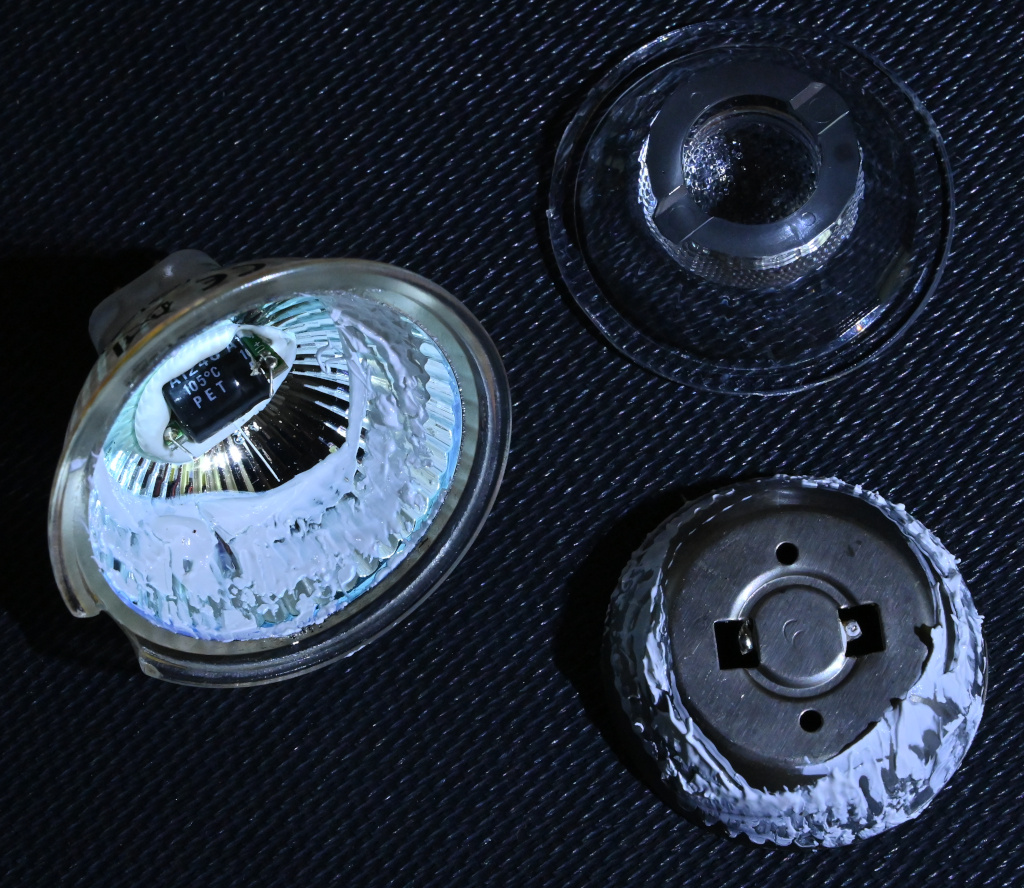
But why so much sticky stuff? It becomes clear after inspecting the “housing”. The glass part looks exactly the same as for a halogen lamp. Even the reflective coating is applied. I guess they didn’t change a thing in the production line for the glass parts when moving from halogen to LED. So it is actually a “double retrofit” – not only in the sense that it replaces a halogen reflector lamp in my house but also in the sense that the supplier retro-fitted an LED in a halogen glass base. Remember the requirement “…has to be cheap”? Never change a running production line.
Now digging deeper into the socket, down to the current converter. I was prepared for the worst. Something like “diode and resistor”. But no, an elco was the first thing I saw. The electronics were glued into the base using silicone. Basically a good choice but difficult to disassemble. Since I didn’t want to use ugly chemistry for dissolving silicone I resorted to brute force, shearing of some components in the process. So no functional check, sorry. Anyway, the circuit is simple enough to guess most of its operation.
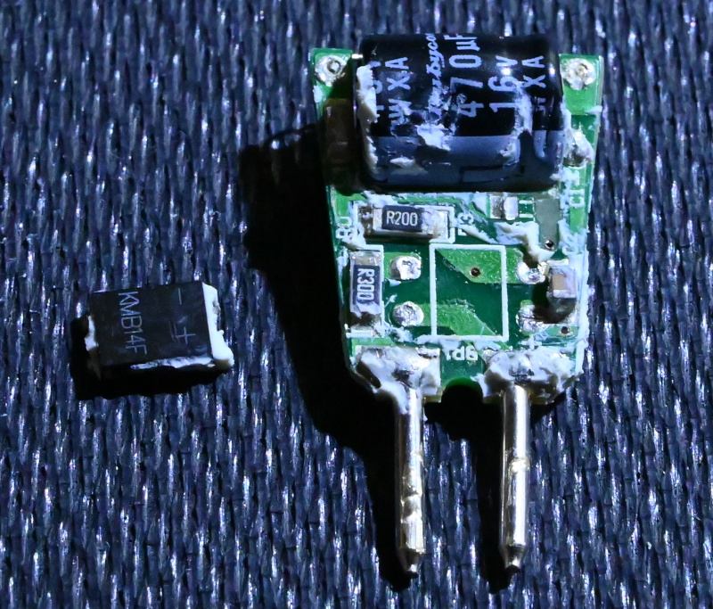
AC voltage on the terminals is bridge rectified and buffered with the electrolytic mentioned earlier. 0.3 Ohm in series with the input limit the inrush current. The bridge seems to use Shottky diodes for reduced voltage drop. The current source is realized with an integrated buck stage and a 0.2 Ohm shunt. A small ceramic (decoupling) a lager ceramic (buck output) a chip resistors (probably defining the current) and a diode (strange, internal FET but external free wheeling diode…) complete the circuit.
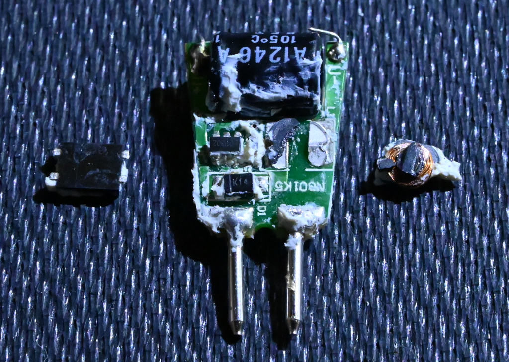
Everything nice and tidy? Well, no. Check the voltage rating of the electrolytic, it says 16V. Back to undergraduate electrics: How to calculate the peak voltage if you have the effective voltage of a sine? Times square root of two. 12V AC gives 17V peak. My 12,85V AC yields 18.2V DC. OK, we have to subtract the Vf of the bridge (two diodes in series, but Shottky), in this case about 0.6 to 0.8V. A little bit more won’t harm? Again no. Two factors reduce the lifetime of elcos: Heat and overvoltage. Here you have an elco running always over spec, placed directly under the LED chip so that it is cozy and warm.
Maybe you wonder which part actually failed. Some connection inside the CoB LED, probably a bond wire. This is a usual failure mode for CoBs if run too hot, either by pressing too much current through or by failing to provide a proper thermal path for cooling. My guess is the second option. But anyway, more sooner than later the dying electrolytic would bring it to an end. So, what lesson can we learn?
Making things cheap will reduce lifetime. I guess the lamp fulfilled all specs when new. But thermal performance is typically not covered by specification for such consumer products. As a consequence design will be as poor as possible – steel “heatsink”, inappropriate glass housing. I can’t tell if lifetime was specified. But even if it was, how should I prove a premature failure?
Retrofitting something simple (halogen lamp) with some electronic gadget (LED retrofit) may make no sense with respect to cost or carbon footprint. Keep the existing system running until natural end-of-life. If you want to invest money to save our climate: Buy “cleaner”, renewable energy. For an 7€ LED lamp you can buy about 80-100kWh which lights your old 20W halogen lamp for more than 5000 hours of continuous operation – 3.5 years of 4 hours every day. If your retrofit breaks earlier, you are at a financial loss.
Although saving energy is in general a good idea, dealing energy for equipment may make things worse concerning CO2 footprint. The carbon footprint of energy production is comparably easy to calculate and can be reduced by favoring wind / solar / water. The carbon footprint of an electronic gadget is nearly impossible to compile because there are so many production steps and commodity trades involved that no one can follow the complete production tree back to the raw materials. I would like to coin a new term for that: Pandora’s Black Box.


Average Rating